

In this guide

Map the drainage route
Mark roof drainage areas, gutter runs, downpipe locations and the final discharge points. Include building corners and any obstacles that require an offset. Hydraulic sizing must suit the project rainfall and roof area.
Avoid missing connections
Check left and right end caps, internal and external corners, connectors, supports, outlets and downpipe elbows. A total gutter length alone does not establish the fittings needed to assemble the system.
Confirm compatibility
Match gutter and pipe shapes, connection sizes, finishes and fixing substrates. Support spacing and outlet capacities belong to the selected system's installation details, rather than a universal spacing rule.
Drainage bill of materials
| Part | Quantity planning |
|---|---|
| Gutter troughs | Schedule each run and the agreed individual lengths |
| Brackets / hangers | According to the selected support detail |
| Left and right end caps | Match each open end of an independent run |
| Internal / external corners | Count each change of direction on the plan |
| Outlets | Match the hydraulically sized discharge locations |
| Downpipes | Schedule height, cross-section and individual lengths |
| Offset elbows | Identify the offset from gutter to wall |
| Pipe clips | Match the wall substrate and support layout |
| Leaf strainers | Optional protection at suitable outlets, with maintenance access |
Coordinate assembly before delivery
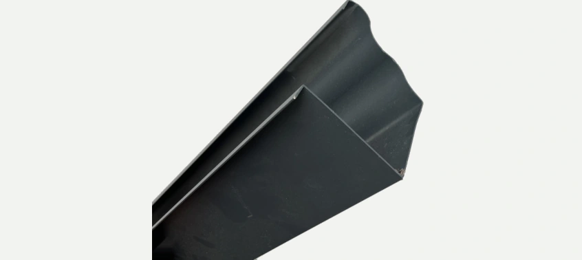
Confirm the fall toward the outlet, support arrangement, joints, sealant and downpipe connections. Available configurations include a 1.0 mm aluminum gutter option in 2 m or 3 m sections; specify the actual supplied section in the order. Run length alone is not enough to size an outlet or determine bracket spacing.
Confirm the right panel and specification with GMiSU.
Send your drawings, dimensions, quantity, color, destination and target schedule for project-based recommendations.